Using Other GPS Receivers With Survey3 Cameras
More accurate geolocation data is never a bad thing when it comes to getting the most accurate outputs from your captured images. That is why we have created this guide on how to setup a GPS other than the ones that come with the Survey3 cameras. If you are using a Cube flight controller please see the relevant guide here.
For Latitude and Longitude:
NMEA messages = $GPRMC or $GNRMC
Baud Rate: 115200
For Altitude:
NMEA messages = $GPGGA
Baud Rate: 115200
If you understand how to program your GPS to the above values, or your GPS already supports them then you can skip the below guide.
There are many options when it comes to choosing a GPS unit. For this guide we will cover how to setup a GPS containing a ublox chip.
1. Download and install u-center application from ublox website.
2. Using a UART to USB converter connect/solder the Power, TX, RX, Ground pins from your GPS to the UART end of the converter, and then connect to your computer via USB. HERE is an example of a UART to USB converter.
3. Launch u-connect. Most GPS default to a baud rate of 9600, so change the baud rate to that:

If your GPS uses a different baud rate, it's most likely 115200.
4. Press the Connect button (outlined in red box below), choosing the COM port for the UART converter if necessary.

5. Go to View at the top, then click Binary Console. If properly connected to the GPS you should see data scrolling up:
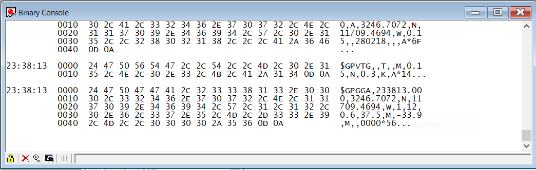
If you don't see information in the console, it's likely you have connected the TX and RX pins opposite either on your GPS or the UART converter. So swap those and see if that fixes the issue.
6. Open the Configuration Window by going to View > Configuration View at the top.
7. To enable the messages, click on NMEA in the left column. Make changes as the below photo shows, namely the Main Talker ID value to GP.

Press the Send button at the bottom of the Configure window.
8. To change the baudrate of the ublox chip click PRT (Ports) in the left column of the Configure Window. Change the Baudrate value to 115200. Press the Send button at the bottom of the Configure Window.

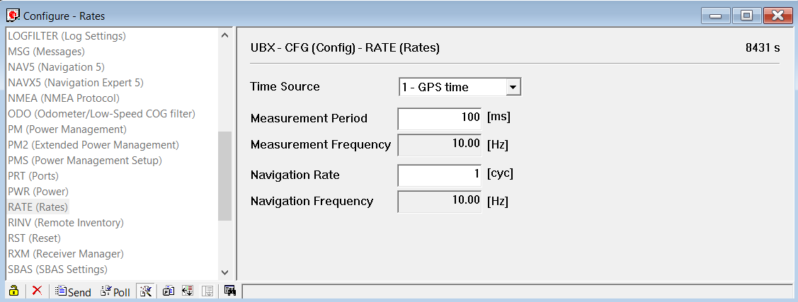
9. Click RATE in the left column of the Configuration Window. Edit the Measurement Period to 100ms. Click Send button at bottom of Configuration Window.
10. To save the changed values to the ublox chip go to Receiver > Action > Save Configuration.
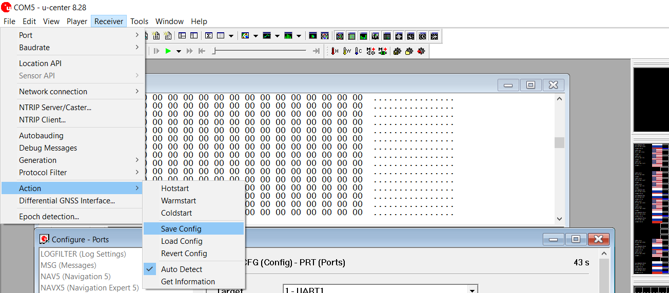
One big thing to mention here is that many GPS receivers do not have a battery on board to allow you to save these changed values. So, you need to use a receiver that has a battery (or add one), otherwise you will need to contact the manufacturer of the GPS receiver to have them send you a custom firmware that has these changes already done (not likely to happen, but maybe they will). To test whether the changes are saved, disconnect the power to the GPS receiver, and reconnect to u-center. Open the Configuration Window and if the values you changed show up, then you're good.
11. That should be it to setup the GPS for the Survey3 camera. Now solder the Power, TX, and Ground pins from your GPS to a USB mini plug. The TX of the GPS goes to the UART_RX pin (pin 3, see diagram below) on the USB plug. If you're soldering to the USB plug/cable that comes with the standard Survey3 GPS the white wire should be the RX.
Once you plug the USB plug into the GPS USB plug on the side of the camera and power it on, you should see the red "GPS OK" text on the camera's back screen. Once the GPS has good 3D lock the camera will beep 6 times (3 pairs of tones) and the text will change green to "GPS Good". That's it, enjoy!


Nolan Ramseyer
Author