Here is a very general work-flow for using point cloud (structure from motion) or any 2D and 3D generating software with images from our cameras:
Step 1: If you captured images in RAW+JPG mode, you'll need to use the Process step of our MAPIR Camera Control (MCC) application to convert the images to TIFF.
Step 2: If you would like to perform reflectance calibration then in MCC choose the "Reflectance Calibration" options.
Step 3: Bring the images into your 2D/3D generation software and process them. For most of these software applications providing the software with good camera calibration values is recommended.
You can find some instructions here for Pix4D or Photoscan.
Survey3 can connect directly to a compatible flight controller to receive the GPS location data. This means you do not need to connect a GPS receiver to the camera and you can use the drone's GPS data. The drone's GPS information is typically corrected for altitude using a barometer, so it is more accurate than the Standard and Advanced GPS receivers for Survey3.
For the Cube flight controller there are two serial ports commonly used: Telem2 (serial 2) and GPS2 (serial 4).
Here are the parameters to change to allow NMEA pass-through from the Telem2 (serial 2) port:
-
set SERIAL2_PROTOCOL to 20 (turns on NMEA pass-through)
-
set SERIAL2_BAUD to 115 (baud rate)
Here are the parameters to change to allow NMEA pass-through from the GPS2 (serial 4) port:
-
set SERIAL4_PROTOCOL to 20 (turns on NMEA pass-through)
-
set SERIAL4_BAUD to 115 (baud rate)
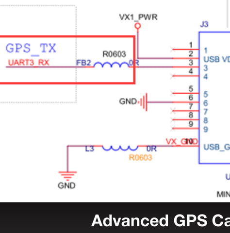
You will want to connect the pin3 on the Survey3 GPS USB port to the MCU_TX pin on the flight controller's serial port:


More accurate geolocation data is never a bad thing when it comes to getting the most accurate outputs from your captured images. That is why we have created this guide on how to setup a GPS other than the ones that come with the Survey3 cameras. If you are using a Cube flight controller please see the relevant guide here.
For Latitude and Longitude:
NMEA messages = $GPRMC or $GNRMC
Baud Rate: 115200
For Altitude:
NMEA messages = $GPGGA
Baud Rate: 115200
If you understand how to program your GPS to the above values, or your GPS already supports them then you can skip the below guide.
There are many options when it comes to choosing a GPS unit. For this guide we will cover how to setup a GPS containing a ublox chip.
1. Download and install u-center application from ublox website.
2. Using a UART to USB converter connect/solder the Power, TX, RX, Ground pins from your GPS to the UART end of the converter, and then connect to your computer via USB. HERE is an example of a UART to USB converter.
3. Launch u-connect. Most GPS default to a baud rate of 9600, so change the baud rate to that:

If your GPS uses a different baud rate, it's most likely 115200.
4. Press the Connect button (outlined in red box below), choosing the COM port for the UART converter if necessary.

5. Go to View at the top, then click Binary Console. If properly connected to the GPS you should see data scrolling up:
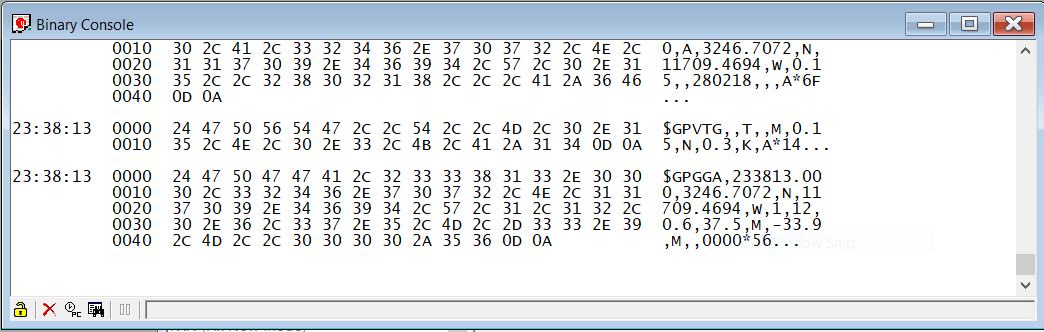
If you don't see information in the console, it's likely you have connected the TX and RX pins opposite either on your GPS or the UART converter. So swap those and see if that fixes the issue.
6. Open the Configuration Window by going to View > Configuration View at the top.
7. To enable the messages, click on NMEA in the left column. Make changes as the below photo shows, namely the Main Talker ID value to GP.

Press the Send button at the bottom of the Configure window.
8. To change the baudrate of the ublox chip click PRT (Ports) in the left column of the Configure Window. Change the Baudrate value to 115200. Press the Send button at the bottom of the Configure Window.

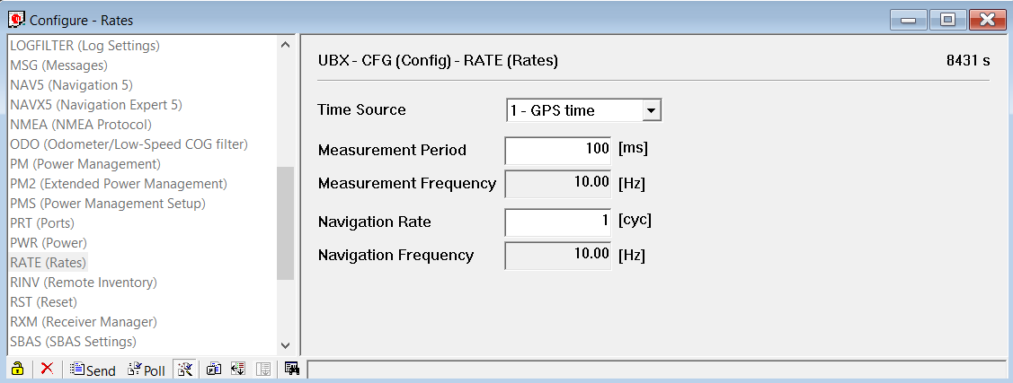
9. Click RATE in the left column of the Configuration Window. Edit the Measurement Period to 100ms. Click Send button at bottom of Configuration Window.
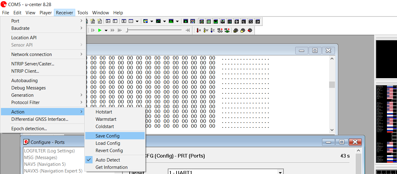
10. To save the changed values to the ublox chip go to Receiver > Action > Save Configuration.
One big thing to mention here is that many GPS receivers do not have a battery on board to allow you to save these changed values. So, you need to use a receiver that has a battery (or add one), otherwise you will need to contact the manufacturer of the GPS receiver to have them send you a custom firmware that has these changes already done (not likely to happen, but maybe they will). To test whether the changes are saved, disconnect the power to the GPS receiver, and reconnect to u-center. Open the Configuration Window and if the values you changed show up, then you're good.
11. That should be it to setup the GPS for the Survey3 camera. Now solder the Power, TX, and Ground pins from your GPS to a USB mini plug. The TX of the GPS goes to the UART_RX pin (pin 3, see diagram below) on the USB plug. If you're soldering to the USB plug/cable that comes with the standard Survey3 GPS the white wire should be the RX.
Once you plug the USB plug into the GPS USB plug on the side of the camera and power it on, you should see the red "GPS OK" text on the camera's back screen. Once the GPS has good 3D lock the camera will beep 6 times (3 pairs of tones) and the text will change green to "GPS Good". That's it, enjoy!

Agisoft Metashape/Photoscan does have camera profiles but it seems it's better to simply enter in some basic information and let the software calibrate it itself.
Under Tools > Camera Calibration, enter the values listed below the photo in the correct boxes:
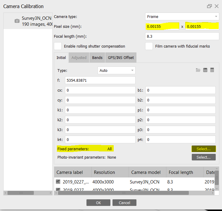
All Models:
Set all camera parameters to fixed.
Turn off "Generic Pre-Selection" during the Align photos step.
Survey3W
Camera Type: Frame
Pixel size (mm): 0.00155 x 0.00155
Focal Length (mm): 3.37
Survey3N
Camera Type: Frame
Pixel size (mm): 0.00155 x 0.00155
Focal Length (mm): 8.25
Survey2 (All Models)
Camera Type: Frame
Pixel size (mm): 0.00134 x 0.00134
Focal Length (mm): 3.97
This guide walks you through the 3DR SOLO hardware and software modifications required to trigger the Survey3/2 cameras from a PWM signal using the Survey3/2 HDMI Trigger Cable.
While easily reversible, the software changes to allow PWM triggering will not allow you to control the GoPro in the 3DR SOLO GoPro gimbal. You will still get live video feed, ability to tilt with the controller and powered stabilization but must start/stop the camera manually.
Disclaimer: Proceed at your own risk, we are not liable for any damage you may cause to your SOLO or camera as a result of these instructions. If you follow everything correctly you will not cause any damage and can easily revert back to the original settings by doing a factory reset.
Step 1: Remove SOLO battery, slide off GPS cover, unscrew the 7 screws holding the battery tray.
Step 2: Cut servo plug off of the Survey3/2 HDMI Trigger Cable. Solder the white cable to PIN19 (PWM7) (orange wire location in below photo) and black cable to GND3 on the SOLO mainboard (brown wire location in below photo):

BE VERY CAREFUL NOT TO BRIDGE ANY PINS WITH SOLDER!
Step 3: Power on SOLO and remote, connect your computer's wifi to the SOLO wifi (Sololink).
Step 4: Open Mission Planner and connect to SOLO (Auto or UDP 115200)
**DO NOT UPDATE FIRMWARE IF ASKED**
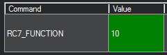
Step 5: Click "Config/Tuning" button at the top of screen. Click "Full Parameter List" on the left. In the search box on the right type "rc7_function". Double click the value box (0) and change to 10. Click "Write Parameter" on the right to save. Click "Flight Data" button at the top, then go back to "Config/Tuning" and "Full Parameter List", searching again for "rc7-function" and make sure the value says 10.
Step 6: At the top click the "Initial Setup" button, click "Optional Hardware" on the left, and then "Camera Gimbal". Change the values for the Shutter section according to the below values and then press ENTER on your keyboard:
RC7
Servo Limits:
Min 1000
Max 1900
Shutter:
Pushed: 2000
Not Pushed: 1000
Duration: 1
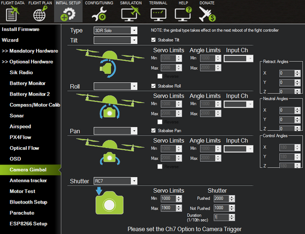
Navigate to "Flight Data" and then back to "Initial Setup" > "Optional Hardware" > "Camera Gimbal" and verify all settings are exactly as the above photo.
Step 7: Turn Survey3/2 cameras on. Click side button (Settings), click front button and navigate to "Time Lapse" and press top button until it reads OFF. Do this for all cameras you want to trigger via PWM.
Step 8: Plug HDMI trigger cable wired to SOLO into the Survey3/2 cameras.
Step 9: Back in Mission Planner go to "Flight Data" screen, right click with mouse anywhere on the map, choose "Trigger Camera NOW" test camera trigger. If the camera(s) does not trigger then you will need to factory reset the SOLO and redo the above steps in Mission Planner.

Step 10: Mission complete... safe flying! :)
This guide walks you through the hardware and software modifications required to trigger the Survey3/2 cameras from a PWM signal using the Survey3/2 HDMI Trigger Cable.
Disclaimer: Proceed at your own risk, we are not liable for any damage you may cause to your UAV or camera as a result of these instructions. If you follow everything correctly you will not cause any damage and can easily revert back to the original settings by doing a factory reset.
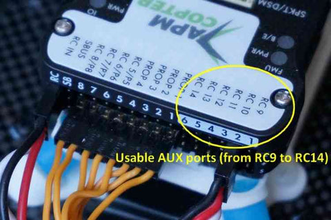
Step 1: Insert servo plug from HDMI trigger cable into Pixhawk AUX PWM port of your choice (typically the second slot, RC10 port). Make sure the white cable is in the bottom PWM signal row of pins just like the below photo:
Step 3: Connect Pixhawk to your computer using USB cable. Open Mission Planner and click Connect button at top right.
Step 4: Click "Config/Tuning" button at the top of screen. Click "Full Parameter List" on the left. In the search box on the right type "rc7_function". Confirm the value is 0.
Step 5: At the top click the "Initial Setup" button, click "Optional Hardware" on the left, and then "Camera Gimbal". Change the values for the Shutter section according to the below values and then press ENTER on your keyboard:
RC10
Servo Limits:
Min 1000
Max 2000
Shutter:
Pushed: 2000
Not Pushed: 1000
Duration: 1
Navigate to "Flight Data" and then back to "Initial Setup" > "Optional Hardware" > "Camera Gimbal" and verify all settings are exactly as the above photo.
Step 6: Turn Survey3 camera on. Choose Photo setting icon in bottom right corner of rear LCD screen. Drag until you see Interval option and change to OFF. Do this for all cameras you want to trigger via PWM.
Step 7: Plug HDMI trigger cable wired to Pixhawk into the Survey3 cameras.
Step 8: Back in Mission Planner go to "Flight Data" screen, right click with mouse anywhere on the map, choose "Trigger Camera NOW" test camera trigger. If the camera(s) does not trigger then you may need to do a factory reset on the Pixhawk and redo the above steps in Mission Planner.
Step 9: Mission complete... safe flying! :)
Pix4D should have built in support for our MAPIR cameras, but sometimes you may need to improve the results. You can follow the below steps to add your own camera profile to the camera database:
Camera Profiles:
Survey3W - Visible Light (RGB)
Survey3N - Visible Light (RGB)
Steps to Add Custom Camera Profiles:
- With Pix4D open go to Help -> Settings -> Camera Database tab -> Export
- Save the camera database xml file somewhere on your computer.
- Open the xml file in a text editor like Notepad (should be able to just double-click to open, otherwise open your text editor and drag the file into the open editor window, File -> Open)
- Download the camera profile that corresponds to your modified camera.
- Open the xml camera profile in your text editor
- Copy the text from the <camera> to the </camera>
- On the camera database file that is open in your editor, paste the copied text after one of the other </camera> lines. If no </camera> lines exist, copy it after the <vendorId value="pix4d"/> line and before the </cameraModelDB> line.
- Save the camera database xml file
- Go to Help -> Settings -> Camera Database tab -> Import
- Select the modified camera database file
- Start a new project or open an existing one.
- Click the Camera icon (Image Properties Editor) at the top left of the main window. If this is a new project, go to the next step.
- Click the "View..." button under the "Selected Camera Model" section.
- Click the drop-down from the "Camera Model Name" and select the profile you have added, which should have a "user" icon (upper half of a person profile icon).
- Select the "OK" button at the bottom and run your project.
Any questions please let us know.


